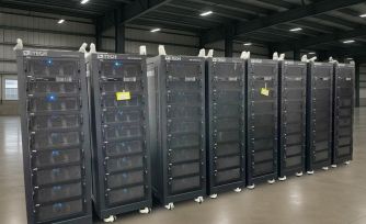
Example of IT6000C bidirectional power supply testing three-level photovoltaic inverter
Application background: With the continuous development of photovoltaic inverter and UPS technology and the continuous expansion of the market, the requirements for inverter efficiency have been more and more valued by manufacturers, and the three-level topology has emerged as the times require. Compared with the traditional two-level structure, the three-level inverter has the advantages of low voltage stress and loss of power devices, good output waveform quality, and high efficiency. It is a new direction for the development of photovoltaic inverter technology.
Working principle of three-level inverter circuit
Each bridge arm of the three-level structure is composed of 4 IGBTs and 6 diodes. The typical topology structure in the following figure is used as an example to analyze the midpoint potential change of the A-phase inverter bridge arm to briefly describe the three-level inverter circuit. working principle.
Typical topology of a three-level circuit
When the two IGBTs of the upper bridge arm of the A-phase bridge arm are turned on, the potential of point A is the same as the positive bus potential, which is U, and the stress platform voltage that each IGBT bears is U/2.
When the two IGBTs of the lower bridge arm of the A-phase bridge arm are turned on, the potential of point A is the same as the negative bus potential, which is -U, and the stress platform voltage that each IGBT bears is U/2.
When the second IGBT of the upper bridge arm of the A-phase bridge arm and the bypass clamp diode are turned on, the A-phase inverter bridge is in the freewheeling state, and the potential of point A is the same as that of the midpoint of the busbar, which is 0.
The three-level structure has one more level than the two-level structure, which can better approximate the sinusoidal output voltage.
Three-level inverter test solution
Since the birth of the three-level inverter, its PWM control technology and the state control of the inverter itself have been the focus of its research. Researchers need high-voltage, high-power and high-performance power test equipment to help them complete the test of new products.
A photovoltaic inverter user adopts the following scheme:
Two sets of IT6018C-800-75 are output in series, the common point Com is grounded to simulate 1/2Vo, 0, -1/2Vo three-level input, and its output terminal is connected to IT7930-350-60 as a grid simulator to simulate the grid environment.
ITECH Three-level Photovoltaic Inverter Test Solution
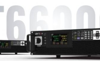
The photovoltaic inverter market is constantly developing towards high voltage and high power. The voltage of IT6000 series power supply products is as high as 2250V, and the maximum power of modular design can reach 1152kW, and the parallel performance does not decrease. It can be flexibly adapted to the testing needs of different specifications of products in scientific research institutes and R&D laboratories of universities. Good performance against ground pressure ensures safety under high-voltage working conditions. IT6000C bidirectional power supply can also be used with SAS1000 solar battery matrix simulation software to realize dynamic simulation of photovoltaic panel output under changing environmental conditions and complete EN50530/SANDIA and other regulatory tests.
In this application, two power supplies need to be used in series and synchronously, and the user can also control the working status of the two devices through the digital I/O interface built into the IT6000C bidirectional power supply. IT6000C digital I/O interface can be set to logic control of high and low level input or output. General I/O functions include controlling device ON/OFF status, displaying device ON/OFF status, prompting/clearing protection status, trigger function bidirectional control Wait. It also supports the customization of various special needs through the wiring of different pins. For example, a pin can be connected to an external instrument, and a fixed pulse or level signal can be set for the external instrument. Once the external instrument fails, the pulse or level signal will be output. After the instrument recognizes the signal, the control power will be turned off. output, improving test security.
IT7900 power grid simulator has 100% rated current source and sink capabilities, 3U 15kVA power output and 350/500V voltage output. Users can expand the power to 960kVA through master-slave paralleling, saving test space. Rich operation modes meet user's single-phase, three-phase, reverse-phase and multi-channel test requirements.
In order to meet the anti-islanding effect certification test of grid-connected products, IT7900 series has developed a professional islanding test mode. Testers can realize the effect of simulating pure resistive or nonlinear grid load by adjusting RLC parameters or configuring active power and reactive power parameters, and further verify the effect of grid-connected photovoltaic inverters in different equivalent impedances, three-phase load balance and Island protection response time in an unbalanced state. This solution can help engineers simplify test circuits and save additional equipment costs such as oscilloscopes and power meters.
Welcome to visit ITECH official website www.itechate.com to download related materials.
Each bridge arm of the three-level structure is composed of 4 IGBTs and 6 diodes. The typical topology structure in the following figure is used as an example to analyze the midpoint potential change of the A-phase inverter bridge arm to briefly describe the three-level inverter circuit. working principle.
Typical topology of a three-level circuit
When the two IGBTs of the upper bridge arm of the A-phase bridge arm are turned on, the potential of point A is the same as the positive bus potential, which is U, and the stress platform voltage that each IGBT bears is U/2.
When the two IGBTs of the lower bridge arm of the A-phase bridge arm are turned on, the potential of point A is the same as the negative bus potential, which is -U, and the stress platform voltage that each IGBT bears is U/2.
When the second IGBT of the upper bridge arm of the A-phase bridge arm and the bypass clamp diode are turned on, the A-phase inverter bridge is in the freewheeling state, and the potential of point A is the same as that of the midpoint of the busbar, which is 0.
The three-level structure has one more level than the two-level structure, which can better approximate the sinusoidal output voltage.
Three-level inverter test solution
Since the birth of the three-level inverter, its PWM control technology and the state control of the inverter itself have been the focus of its research. Researchers need high-voltage, high-power and high-performance power test equipment to help them complete the test of new products.
A photovoltaic inverter user adopts the following scheme:
Two sets of IT6018C-800-75 are output in series, the common point Com is grounded to simulate 1/2Vo, 0, -1/2Vo three-level input, and its output terminal is connected to IT7930-350-60 as a grid simulator to simulate the grid environment.
ITECH Three-level Photovoltaic Inverter Test Solution
The photovoltaic inverter market is constantly developing towards high voltage and high power. The voltage of IT6000 series power supply products is as high as 2250V, and the maximum power of modular design can reach 1152kW, and the parallel performance does not decrease. It can be flexibly adapted to the testing needs of different specifications of products in scientific research institutes and R&D laboratories of universities. Good performance against ground pressure ensures safety under high-voltage working conditions. IT6000C bidirectional power supply can also be used with SAS1000 solar battery matrix simulation software to realize dynamic simulation of photovoltaic panel output under changing environmental conditions and complete EN50530/SANDIA and other regulatory tests.
In this application, two power supplies need to be used in series and synchronously, and the user can also control the working status of the two devices through the digital I/O interface built into the IT6000C bidirectional power supply. IT6000C digital I/O interface can be set to logic control of high and low level input or output. General I/O functions include controlling device ON/OFF status, displaying device ON/OFF status, prompting/clearing protection status, trigger function bidirectional control Wait. It also supports the customization of various special needs through the wiring of different pins. For example, a pin can be connected to an external instrument, and a fixed pulse or level signal can be set for the external instrument. Once the external instrument fails, the pulse or level signal will be output. After the instrument recognizes the signal, the control power will be turned off. output, improving test security.
IT7900 power grid simulator has 100% rated current source and sink capabilities, 3U 15kVA power output and 350/500V voltage output. Users can expand the power to 960kVA through master-slave paralleling, saving test space. Rich operation modes meet user's single-phase, three-phase, reverse-phase and multi-channel test requirements.
In order to meet the anti-islanding effect certification test of grid-connected products, IT7900 series has developed a professional islanding test mode. Testers can realize the effect of simulating pure resistive or nonlinear grid load by adjusting RLC parameters or configuring active power and reactive power parameters, and further verify the effect of grid-connected photovoltaic inverters in different equivalent impedances, three-phase load balance and Island protection response time in an unbalanced state. This solution can help engineers simplify test circuits and save additional equipment costs such as oscilloscopes and power meters.
Welcome to visit ITECH official website www.itechate.com to download related materials.