Application of the IT2705 Modular DC Power Analyzer in LiDAR Systems
Industry Background With the rapid development and widespread adoption of autonomous driving, trends such as the miniaturization, electrification, and chip-integration of LiDAR (Light Detection and Ranging) systems are gradually emerging. LiDAR is a laser-based detection and ranging system that uses a laser as the light source and employs optoelectronic detection techniques as an active remote sensing device.
As a critical sensor in modern automotive, intelligent transportation, and industrial inspection applications, its reliability directly impacts the safety and stable operation of the entire system. To ensure that LiDAR products operate accurately and reliably under various complex environments, it is essential to establish a comprehensive reliability testing protocol.
Vertical-Cavity Surface-Emitting
Laser (VCSEL)
VCSELs are a type of semiconductor laser characterized by laser emission
perpendicular to the chip surface. In LiDAR systems, VCSELs serve as key
components responsible for generating and emitting laser beams, which are used
to detect the distance, velocity, and other information of target objects.
VCSELs offer advantages such as compact size, low power consumption, and easy
integration, making them widely adopted in the LiDAR field.
Testing Requirements and Challenges
The testing of VCSELs and VCSEL arrays involves a series of critical electrical
performance parameters, including forward voltage, linearity, threshold
current, output optical power, and slope efficiency of the laser diode. LIV
testing (Light-Current-Voltage) is a fast and straightforward method commonly
used to determine these key performance characteristics of VCSELs.
- L – Light Output Power: Measures the output optical power of the laser.
- I – Drive Current: The current injected into the laser.
- V – Forward Voltage: The voltage drop across the laser terminals.
This test combines two measurement curves into a single graph, illustrating the dependence of laser output intensity on operating current, as well as the relationship between the applied voltage and operating current. Through LIV testing, the electrical characteristics of the VCSEL can be comprehensively evaluated, and its optimal output optical power can be determined.
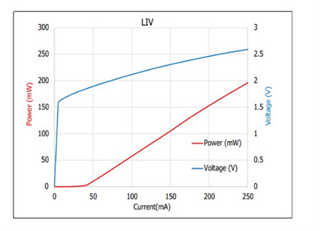
LIV curve diagram
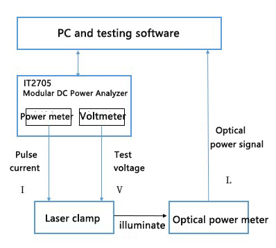
LIV Test Schematic Diagram
Key Testing Challenges
· High-Speed Modulation Requirement: 3D sensing applications, such as LiDAR and Time-of-Flight (ToF) systems, require VCSEL devices to support high-speed modulation, necessitating high-speed pulse testing.
· Self-Heating Effects: High-speed, high-current operation can easily lead to self-heating in the device, requiring precise control of the pulsed current waveform.
· High-Speed, High-Precision Data Acquisition: Testing demands fast and accurate data acquisition with real-time graphical display of results.
· Multi-Channel VCSEL Array Testing: Testing VCSEL arrays involves multiple channels, which occupy significant space and require careful system integration.
· Built-In Current Protection: Integrated current protection is necessary to prevent laser overload and potential device damage.
Advantages of the IT2705 Solution
The IT2705 is a highly integrated, modular DC power analysis platform specifically designed for semiconductor precision testing, dynamic power consumption measurement, battery behavior simulation, and power characteristic research in R&D environments. It combines DC power supply, electronic load, arbitrary waveform generation, oscilloscope sampling, and data recording functionalities within a single platform, and features an intuitive graphical user interface for streamlined operation.
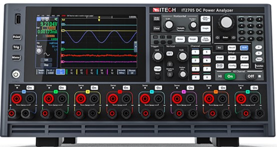
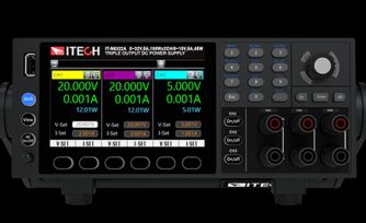
IT2705 DC Power Analyzer
1. IT27814 Pulse Output
The IT27814 module delivers output of ±20 V / ±3 A / ±20 W and is equipped with a high-performance arbitrary waveform (ARB) output capability. It supports user-defined output sequences, allowing voltage, current, power, or resistance to vary over time according to customized profiles.
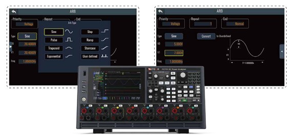
IT2705 Arbitrary Waveform Generation Function
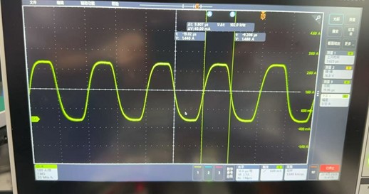
IT27814 measured 0-3A pulse width: 10µs
2. High-Speed, High-Precision SMU with Advanced Oscilloscope Functions
All IT2705 modules feature a high-speed oscilloscope sampling rate of up to 200 kHz, supporting high-bandwidth, real-time monitoring of DUT voltage, current, and power waveforms. The data acquisition function allows a minimum sampling interval of 20 µs. The IT27814 module achieves a resolution of up to 6 µV / 0.1 nA, offers four current ranges, and supports seamless switching between current ranges.
3. Flexible Modular Design
The IT2705 supports up to eight modules of different types—including DC source, bidirectional source, regenerative load, and SMU modules—operating collaboratively within a single system. This enables unified control and monitoring of input, output, and load, eliminating the complexity of integrating multiple instruments. When configured with eight IT27814 modules, the system provides full 8-channel SMU functionality.
Individual module power ranges from 20 W to 500 W. The SMU modules also support master-slave parallel operation under constant current (CC) mode, allowing power expansion to enhance equipment utilization and testing range, while reducing cost and footprint.
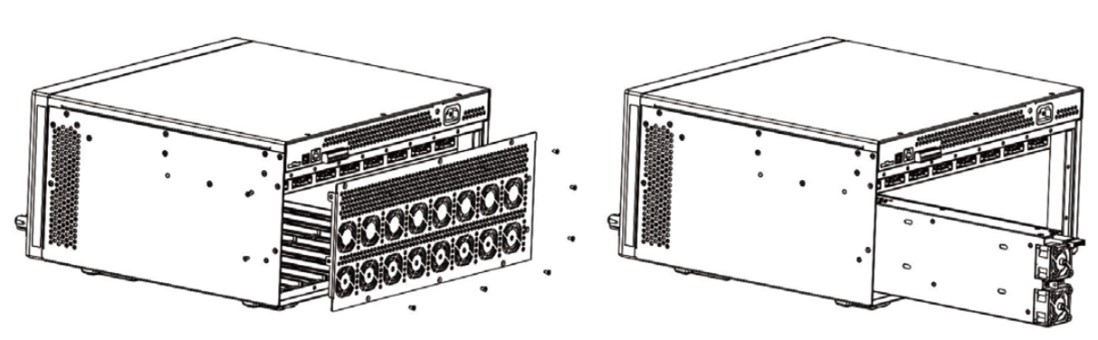
IT2705 DC Power Analyzer Module Insertion Diagram
4. Versatile and User-Friendly Control Software
PV2700 is a graphical control and analysis software developed specifically for the IT2705 modular DC power analysis system. It provides an intuitive interface, allowing users to quickly configure output parameters, control channel states, and execute various waveform outputs and automated test sequences.
Conclusion
The IT2705 DC Power Analyzer is an innovative “all-in-one” solution that integrates multiple instrument functions into a single platform. With its graphical interface and flexible module combination, engineers can easily capture critical data that is difficult to measure using traditional methods, such as microamp-level standby currents and millisecond-level transient peak currents. This capability enables in-depth product optimization and significantly enhances R&D efficiency.
For more information, please visit the ITECH official website: https://www.itechate.com